
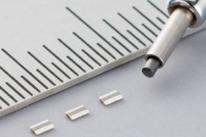
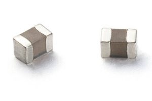
“The mounting area is reduced by approximately 55% over general 0201 [0603 metric] products to just 0.08mm2.” according to the company. “Moreover, a built-in transient voltage suppressor protection element ensures high ESD resistance.”
They are rated at 3.6V, with the internal bi-directional TVS breaking down between 8.2 and 9.2V.
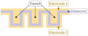
Trenching is used to increase capacitance per unit area, and, being made from silicon, the devices step outside the usual three-character ceramic capacitor temperature coefficient labelling system. Operation is over -55 to +150°C with a ±250ppm/°C coefficient. Capacitance tolerance is ±15%.
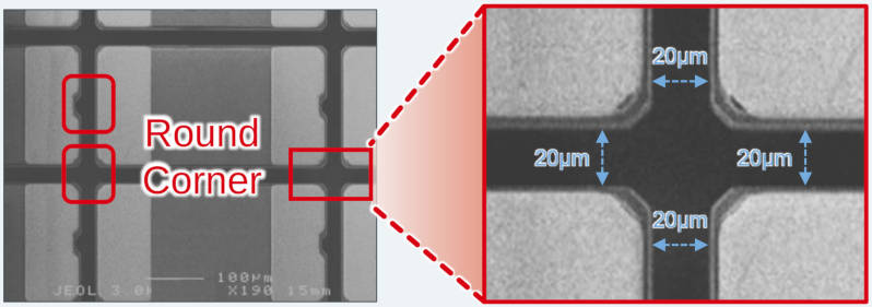 “Miniaturisation technology allows processing in 1µm increments that eliminates chipping during external formation and improves dimensional tolerances within ±10µm,” said the company. “This small variation in product size enables mounting with a narrower distance between adjacent components. At the same time, the backside electrode used for bonding to the substrate has been expanded to the periphery of the package to improve mounting strength.” Total pad area for bonding is ~0.032mm2.
Two parts are available, with five more following:
| BTD1RVFL102 | 1,000pF |
| BTD1RVFL681* | 680pF |
| BTD1RVFL471 | 470pF |
| BTD1RVFL331* | 330pF |
| BTD1RVFL221* | 220pF |
| BTD1RVFL151* | 150pF |
| BTD1RVFL101* | 100pF |
*under development
Applications are foreseen in smartphones and wearables.
A second series, scheduled for introduction next year, is being developed with improved high-frequency characteristics (lower ESR and lower loss) for RF applications, and then a higher voltage third generation is planned for industrial and automotive use in 2026.
£5 each at Mouser ! Obviously a samples price (which should be free guys !) but don’t think I’ll be designing these in quite yet.
Afternoon Mike
£5?
Maybe not wearables then, or is Rolex going to make a smart watch…? 🙂
It is nice to see the flat capacitance vs. DC bias plot, but I would also like to se a |Z| vs frequency plot. I am not sure how to use the built-in TVS.