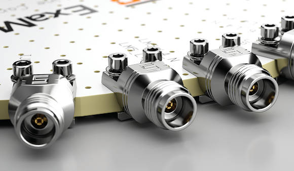
They measure only 9.5mm from side-to-side where they sit on the PCB and are under 8mm from top to bottom (see photo)
“These connectors are commonly used in a lab setting for high-frequency test and measurement and evaluation boards,” according to the company.
There are three series:
- 185-EL dc to 67GHz – 1.85mm
- 240-EL dc to 50GHz – 2.40mm
- 292-EL dc to 40GHz – 2.92mm
In each case, the millimetre dimension is the inner diameter of the outer part of the coaxial signal path.
The connectors bolt to the PCB through two holes, using provided screws and a tapped strengthening plate, also provided, for the underside of the board (just visible in photo).
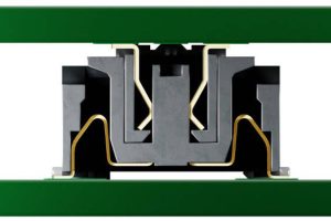
Electrical connection with the board is to a pattern of top-side conductors for the signal and ground, onto which are compressed a pattern of gold-plated contacts on the connector when its screws are tightened – making it a form of surface-mount.
It is “easy to align the launch pin with the circuit trace, which also helps to ensure proper ground alignment for preventing RF leakage”, according to the company, which claimed: “Proper alignment and the removal of solder allows for increased signal integrity versus soldered edge launch, or even vertical or angled launch connectors.”
Connectors can be attached, removed, and reattached to the PCB up to 500 time without damaging the PCB, it claimed.
Recommended board thickness is 0.04 to 0.1inch (~1-2.5mm) and recommended screw mounting torque is 0.5 – 0.8inch-lbs (~0.06 – 0.09Nm).