
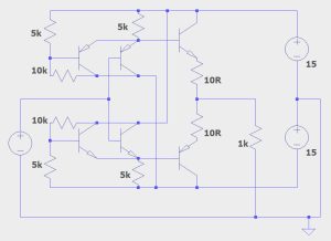
Now the brain is back to some extent, I noticed a whole genre of transistor that I was ignorant of, and it seems to solve one of the short comings of the bargain-basement pulse-generator output buffer I thought-up a while ago (right).
A modification of a ‘diamond buffer’, it has two added transistors that set the maximum and minimum output voltage by emitter-switching – just set the maximum and minimum voltages on the two bases – done by the two 5k-10k potentiometers in the diagram.
The problem is that, under certain circumstances, the bases of the transistors whose emitters are tied (so in two places) will be pulled in opposite directions far enough that one or other of the base-emitter junctions will avalanche (or Zener) and freeze the output unwantedly.
What is needed are transistors with a high enough reverse base-emitter break down (Vebo) for any voltage expected.
Vebo is normally around 5V, but if this thing was to need produce a ±12V output, for example, higher Vebo values would be required.
And that is where ‘muting’ and ‘chopping’ bipolar transistors come in, as they are optimised for working with high reverse voltages across their base-emitter junctions (and probable other things).
I had no idea that there were special transistors for either of these, and believe that lower emitter doping levels are part of the trick.
Btw, muting transistors are designed specifically for briefly grounding the outputs of audio signal processing circuits at switch-on to prevent a ‘thump’ being passed on to loudspeakers – the rest of the time the base is effectively open-circuited and the transistor is expected not to leak into the signal nor add much capacitance.
Dave Jones did an excellent EEVblog describing protection circuits in Fluke multimeters, where pairs of high Vebo blanking transistors are used in pairs to make a very-low-leakage ~25V bipolar clamp for input lines. I think he mentions the 2SC3326, which is a Vebo=25V muting transistor.
Also, he uses Mouser’s transistor search which allows Vebo to be selected for, but I notice that this also brings up incorrect transistors because in some cases the Vebo box in the database has been filled with the collector-base voltage instead emitter-base voltage.
Resources:
There is an interesting short article on blanking transistors on electroschematics, and bitsavers has a copy of Motorola app-note AN-0470 about chopping transistors which goes into high Vebo theory, and mentions the 2N2944A chopper transistor and the MM4052 ‘bilateral switching transistor’ (!) – even my 1989 Motorola transistor data book jumps from MM4037 to MM4258…. The only reference I can find is here, on AllTransistors (link of unknown providence) where Vcb=Veb=Vce=30V.
Other known blanking transistors seem to be 2SD1915, 2SC2878 (Toshiba) and 2SD2407K (Rohm) – the product page of another Rohm transistor (2SD2114K, 12Vebo) specifically mentions muting.
Lastly, this hi-fi discussion on DIYaudio has some wise comenters.


The old-school comparators LMx39 & LMx93 have huge differential input voltage limits (+/-36V) and in the case of the LMx39 can go beyond the supply rails. The input stage schematic provided on the datasheet suggests this voltage is blocked by the B-E junction of just **one** of the four input transistors (ie: depending on the polarity of the applied voltage, it is one of the two PNPs behind the one connected to the input, as these are Darlingtons).
I’ve often wondered what are the design trade-offs to building a BJT with a very large reverse Vbe withstand rating.
Oh, and the link to the “bargain-basement pulse-generator” seems to be broken.
Cheers.