An optical time-domain reflectometer (OTDR) is a fibre optic network test instrument that measures the characteristics of an optical fibre. It can determine the fibre’s length and attenuation and detect a variety of fault types.
The network test instrument works by firing pulses of infrared (IR) light along the cable and measuring the reflections and scatter coming back.
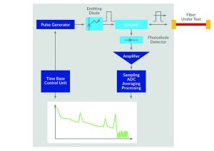
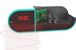
Figure 1: The functional blocks of a typical OTDR (source: Viavi Solutions)
The functional blocks of a typical OTDR are shown in Figure 1. The laser diode, photodetector and signal processing capabilities are critical functions in determining performance parameters.
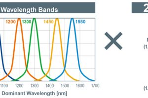
The operating wavelengths for single-mode fibres are typically 1,310nm and 1,550nm. The instruments allow switching between these wavelengths. Often 1,310nm is best for finding fibre alignment problems and 1,550nm is typically used for identifying bending or cracking issues in the fibre. Comparing reflection and scatter results at both wavelengths can help determine the nature of faults.
Determining range
An OTDR’s dynamic range is one determinant of its measurement range of the OTDR. Both are dependent upon the laser pulse width, wider pulses enabling greater range and the wavelength of the pulses. Instruments with a 50dB dynamic range might have a measurement range of up to 125km at 1,310nm and up to 220km at 1,550nm.
The measurement range specifies the overall distances that the OTDR can measure. It is related to the dynamic range, but represents the total span of the measurement. The measurement range is inversely proportional to the signal attenuation along the fibre and directly proportional to the dynamic range of the instrument. It is affected by the characteristics of the components in the OTDR, not least the laser and photodetector and its processing algorithms.
Dead zones of two distinct types are specified. Event dead zones, sometimes called event blind areas or reflective dead zones, concern an OTDR’s ability to detect closely spaced events. Two faults close together may be interpreted as a single fault by the instrument. The event dead zone is usually less than 2m. The attenuation dead zone, or attenuation blind area, is typically a few metres longer. It refers to the length of an optical fibre immediately following a high-loss event, such as a splice, bend, or other discontinuity, where the OTDR is unable to accurately measure or detect changes in the optical signal due to the attenuation caused by the issue.
Both types of dead zone vary with pulse width, shorter pulses reducing the distance. The recovery speed of an instrument’s photodetector after receiving a pulse, particularly if the pulse momentarily overloads the device, is key to minimising the dead zones.
Selection criteria
The pulse width determines the duration of the optical pulse emitted by the OTDR’s laser diode. The chosen pulse width is proportional to the distance being measured and where there are splitters along the network fibre under test, wider pulses are needed to account for the attenuating effect of these.
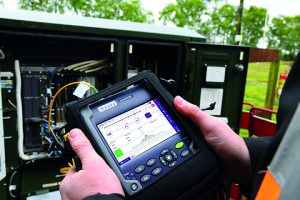
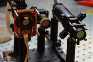
Figure 2: Portable testers, such as the SmartOTDR, are used in the field
(Picture credit: Viavi Solutions)
Sampling resolution is the distance between individual data points along the length of the fibre. A higher sampling resolution provides more detailed and accurate measurements.
Other selection criteria include the type of display on the instrument, the fibre connectivity supported (typically at least SC, LC, and FC connectors) and, particularly for field use, the size, weight, battery life and cost of the OTDR.
Laser diodes and photodetectors
Pulsed laser diode modules for OTDR applications may output anything from around 5mW to over 500mW at 1,310nm-1,550nm. Despite these relatively small power levels, the total power consumption of the modules is often several Watts, necessitating the use of heatsinks and thermal management electronics. Effective thermal management is necessary to maintain accuracy because the electrical characteristics of photodetectors may vary significantly with temperature.
The detector for sensing IR light returning to the OTDR is a photodiode that converts light to an electrical current. Avalanche photodiodes (APDs) can multiply the current produced by incident light using the avalanche effect. APDs amplify the small photocurrent signals to boost system range. Some types, single photon avalanche diodes, are so sensitive that they can amplify the current generated by a single photon to produce a measurable signal.
InGaAs APDs
Silicon APDs are most responsive to wavelengths from 600-800nm, but may be useable anywhere between 200nm and 1,100nm, depending on the application. The multiplication factor, that is how much they amplify the current generated from incident light, is usually set between 50 and 1,000 by adjusting the device’s reverse bias voltage. The high absorption and dispersion of glass optical fibres at these wavelengths means they have limited use in OTDRs.
For wavelengths from 1,100nm-1,700nm, where optical fibres have low absorption and dispersion, APDs based on germanium or indium gallium arsenide (InGaAs) are used. InGaAs APDs exhibit lower noise and higher detection bandwidth than germanium devices, but the maximum gain to which they can be set is normally between only 10 and 40 before the amplified noise becomes problematic for the transimpedance amplifier (TIA) connected to the APD. The TIA is a signal conditioning circuit that converts the current from the APD into a voltage. This output is then fed into an ADC for further signal processing in the digital domain before results are displayed graphically on the OTDR’s screen.
‘Noiseless’ InGaAs APDs
Eight years of research at the University of Sheffield has resulted in a new class of InGaAs APD technology. Through the addition of antinomy alloys, the APDs demonstrate up to 12x higher sensitivity than traditional InGaAs components. They can be operated with APD gains over 120, exhibit fast overload recovery, have 10-times lower temperature drift than parts without antinomy and show stable high-temperature performance.
These ‘noiseless InGaAs APDs’, while not strictly noise-free, exhibit a reduction in noise compared with other best-in-class InGaAs APDs greater than an order of magnitude. Phlux defines ‘noiseless’ APDs as those with an excess noise factor low enough to achieve an APD gain of over 100 without signal-to-noise degradation. (Noiseless is a relative term, points out the company, similar to the definition of alcohol-free beer as any containing less than 0.05% alcohol by volume.)
Improving OTDRs
The design of OTDRs varies widely, based on the performance of active and passive components and the quality of optics, cabling and interconnect. Initial estimates of the impact of APDs based on this new compound semiconductor technology suggest that for a typical professional instrument, the operating range could be extended by up to 50% or the sampling rate increased by a factor of up to 12 for a given laser power.

Figure 3: Responsivity curves for Si, Ge and InGaAs APD technologies
Alternatively, the power of the laser diode could be reduced significantly by simply changing the photodetector, without reducing the instrument’s range. This would simplify thermal management and ease the demands on optical components, both of which could reduce the size and cost of the infrared elements of the design. These reductions have been estimated at up to 30% and 40% respectively. The thermal stability of the new APD technology promises more accurate measurements across varying environmental conditions and its faster recovery times compared with conventional InGaAs APDs should reduce both types of dead zone.
Not all these benefits can be achieved simultaneously; there will be design trade-offs, but rarely, if ever, has changing a single diode had such profound implications for so many parameters in a sophisticated piece of test equipment.