Figure 1: Inductance curve of an inductor, the WE-TCI 0402 15nH (744901115)
High frequency inductors are used in a variety of industries, from consumer products to highly specialised scientific applications. Typical functions include resonance tuning, impedance matching, filtering and attenuation of high frequency overshoots in electronic switching. More specialised applications include radar, GPS and test equipment.
Properties of RF inductors
RF coils work just like any other coil. The same physical rules apply to them as to power inductors. Therefore, they can still be characterised by their windings, permeability, inductance, tolerance, DC resistance and rated current. However, there are additional parameters, such as the quality factor, which are crucial for validating the RF inductance in a particular function.
The inductance is the most important parameter. As with conventional inductors, this parameter is determined by the relative permeability of the core, its cross-sectional area, the number of turns and the effective magnetic path length of the field lines in the core, as in the equation:
 With inductance L [H], relative magnetic permeability µr, magnetic permeability of the free space µo (4π·10-7 Vs/1 Am), effective cross-sectional area of the coil core Aeff [m2], effective path length of the magnetic field lines in the coil core Leff [m] and number of windings N.
The reason why most RF inductors have a ceramic or ‘air core’ is due to the low permeability required, which also enables high inductance stability, high Q and low losses. Both ceramics and air have no magnetic properties, that is, their relative magnetic permeability (µr) is ≈ 1 and therefore does not influence the magnetic behaviour of the inductor. According to the inductance equation of a coil, if µr ≈ 1, the inductance value can increase only with the number of turns or the dimensions of the coil. This is why RF inductors with ceramic or air cores achieve inductance values only in the nH range. As the number of turns increases, the parasitic parameters increase, which can reduce the quality Q and the natural resonant frequency. In cases where larger inductance values in the µH range are required, ferrite cores with a magnetic permeability µr > 1 are required.
It is very important in RF design to maintain tight inductance tolerances, especially in applications such as filtering, matching and in oscillator circuits. This is why many engineers appreciate tighter tolerances, even if they come at an extra cost. Specifications will state both the inductance value and the tolerance at a given frequency point. In most RF applications, such as high order filters, oscillator circuits or impedance matching, it is very important that the inductance curve is as flat as possible over a wider frequency range (Figure 1). Furthermore, the inductance value should be independent of the current.
Self-resonance frequency
As the winding structure of each wire coil has a certain capacitance, the inductor represents a parallel resonant circuit that has a corresponding self-resonance frequency (SRF). As with conventional inductors, the SRF indicates the frequency up to which the component behaves like an inductor. Exactly at the SRF, the inductance with its parasitic capacitance behaves like a resonant circuit with an almost infinitely high impedance; only circuit losses limit the high value of the impedance. Beyond the SRF, the component behaves like a capacitor (Figure 2).

Figure 2: Inductance (L, black) and impedance (|Z|, red) of an inductor, the WE-RFH 1008 0.56nH (744758256A)

Figure 3a: Schematic of an RF inductor. Parallel wires act like electrodes of a capacitor generating a distributed capacitance
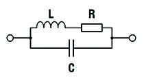
3b: Equivalent circuit of a RF inductor: L represents the inductance, R the losses of the wire and C the distributed capacitance
As shown in Figure 3a, there is a distributed capacitance between the windings and the connections (contact pads) of an inductor, which leads to the equivalent circuit shown in Figure 3b. The relationship between the inductance (L), the distributed capacitance (Cp) and the SRF is shown in the equation:
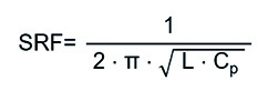 With self-resonance frequency SRF [Hz], inductance L [H] and distributed capacity CP [F].
The SRF is therefore the frequency point at which the parasitic capacitance forms a parallel resonance with the inductance. In other words, the frequency point at which the capacitance cancels the inductance (that is, XL = XC). Equation 2 also shows that increasing the inductance and/or parasitic capacitance lowers the SRF and vice versa. This is the reason why the higher the inductance value, the lower the SRF.
In EMC filter applications where inductors are used, the best signal attenuation occurs just below the SRF, where the impedance is very high and therefore the attenuation reaches its maximum. In signal filtering or impedance matching applications, it is more important to have a constant inductance in the relevant frequency range, which means that the SRF of the inductor should be well above the operating frequency of the circuit. A rule of thumb is that SRF is greater than eight- to 10-times the circuit frequency.
As a general rule, the higher the inductance value, the lower the SRF, as the winding capacitance of the inductor increases. Other influences on the SRF are stray capacitances of the circuit, the components to which the inductor is connected and the type of PCB used in the application. PCB parameters such as εr and laminate thickness reduce the SRF of the inductor. Solder pads, traces, ground and VCC planes also affect the SRF.
Quality factor Q
The quality factor Q is an essential characteristic parameter and one of the first things every RF engineer should consider. Depending on the manufacturer, the Q factor is specified either as a minimum value or as a typical value at a specific frequency point.
The Q factor is the ratio between the reactance XL and the losses RS and is an indicator of suitability (shown in the equation below). For inductors with air or ceramic cores, the resistance (RS) is mainly due to the specific resistance of the conductor in the coil. A higher Q factor means fewer losses in the component.
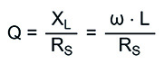 With quality factor Q, reactance XL [Ω], resistance RS [Ω], inductance L [H] and angular frequency ω = 2πf [Hz].
Inductors with a ferrite core do not have a constant inductance over the frequency, and the quality factor cannot simply be calculated using the above equation. For a correct measurement of the quality factor, the frequency-dependent real and imaginary losses of the ferrite material must be taken into account in the measurements, together with the various inductance and capacitance effects of the composite materials of the inductor.
In broadband applications where chokes are required to attenuate an RF signal spectrum, it may be necessary to use an inductor with a ferrite core. In this application, the resistive (Ohmic) part of the magnetic permeability of the ferrite is taken into account, which represents the losses of the ferrite material. By using a choke with a lossy ferrite core, the required attenuation can be achieved over the desired frequency range. The disadvantage is that this component contributes to the overall losses of the circuit.
The DC resistance is the most obvious contribution that influences the Q factor of an inductor, but there are other effects, such as skin effect, core losses and radiated energy, which also contribute.
DC resistance
RDC (or DCR) is the Ohmic resistance of the inductor, in particular of the wire. The value describes one source of power loss of the inductor. Although the losses from skin effect and proximity effect are greater at higher frequencies than those caused by DC resistance, the RDC is a good starting value for evaluating the losses of an RF inductor. The RDC is defined in the specifications as the maximum possible value either in Ω or in mΩ.
Rated current
IR indicates the current at which the inductor increases its temperature by a certain amount (ΔT). In standard RF applications the current is usually low, so this parameter plays a subordinate role. For applications where higher currents are required a high-current inductor series is required. The temperature rise plus the ambient temperature must not exceed the maximum operating temperature.
RF Inductor
See also: Automotive-grade power inductors work up to 150 °C