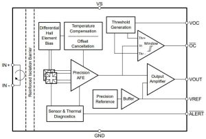
Aimed at electric vehicle chargers and with versions available up to 75Arms, isolation in the TMCS1123 is rated at 1.1kVdc, and to withstand 5kVrms.
“Assessment of device lifetime working voltages follow VDE 0884-11 for reinforced insulation, requiring time-dependent dielectric breakdown projection failure rates of less than 1ppm, and a minimum insulation lifetime of 30 years,” said TI. With safety margins included, it added, the design goal is a minimum lifetime of 39 years at 900Vrms.
Maximum sensitivity error is ±0.75% according to the company, which said: “The high precision and stability over lifetime remove the need to recalibrate equipment.”

For control loops, the parts have a bandwidth of 250kHz and a 600ns propagation delay.
The current path is made from lead-frame, and has a nominal resistance of 0.67mΩ at 25°C.
There are five versions rated at 25, 50, 75, 100 or 150mV/A, then each of those has three versions, with the output centred at 2.5, 1.65, or 0.33V – the centring reference voltage is brought out on a pin for the following signal processing.
Running the ICs on 5V gives the highest range – up to ±96A. Some supply / centre voltage combinations result in asymmetric ranges – see table 5-1 in the data sheet.
All of them come in the same 10.3 x 10.3 x 2.65mm SIOC package, modified with just two long current legs on one of the sides.
“As a result of the electrostatic shielding on the Hall sensor die, only the magnetic field generated by the input current is measured, thus limiting input voltage switching pass-through to the circuitry,” said TI. Regarding magnetic fields: “ambient field rejection limited only by Hall element matching and package lead-frame coupling reduces errors from stray fields by more than 40dB”.
 Electronics Weekly Electronics Design & Components Tech News


