With RF devices becoming ever more ubiquitous, knowing how to make fast, flexible, RF measurements is vital.
As the saying goes, a chain is only as strong as its weakest link, and in the same way an RF measurement is only as reliable as the most uncertain component or practice.
Exceptional accuracy and flexibility have made the vector network analyser (VNA) the instrument of choice for many RF measurements.
A VNA may be one of a number of instruments used in a test system. In this case, RF networks are considered to be a series of interconnected electrical components, not to be confused with wireless or computer networks.
To fully realise these benefits, you must understand the weaknesses of your measurement, correcting or minimising them where possible.
Correct for systematic errors
Understanding the error sources in any RF measurement setup is a prerequisite to making accurate measurements.
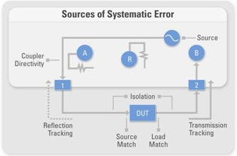
Like all RF instruments, network analysers require a certified calibration laboratory to perform a yearly factory calibration. However, the key to the exceptional measurement accuracy achieved by network analysers is performing a user calibration more frequently. (See Figure 1) This can correct smaller errors that will occur between major calibrations.

Common systematic errors;
1) Transmission and reflection tracking – Frequency response errors, or transmitted and reflected signal loss, result across all frequencies and must be characterised and corrected.
2) Source and load mismatch – Many RF systems have a characteristic impedance of 50?. To properly measure the impedance of the Device Under Test (DUT), any impedance errors in the system must be accounted for.
3) Isolation – Errors can occur from crosstalk between various components in the test setup, VNA ports and measurement reference planes.
4) Coupler directivity – VNAs rely on directional couplers to separate the transmitted signals from the reflected signals. Ideally, a directional coupler measures the forward or reverse travelling signals and produces no output for signals travelling in the opposite direction. Because this is rare, the coupler leakage must be accounted for.
To correct for these systematic errors, you can perform a user calibration and measure a set of known standards.
Next compare the measured value to the value of the known standard to calculate the error for each data point, and finally apply the appropriate error correction for each frequency point in the measurement. Using broadband Short, Open, Load and Through (SOLT) standards is a common, accurate calibration method for RF frequencies.
Many factors determine how often a user calibration is performed including the required measurement accuracy, environmental conditions and the repeatability of the DUT connection. A fresh user calibration may be necessary hourly or weekly.
You should use verification standards or the less stringent practice of measuring a “golden DUT”. A golden DUT is a DUT which has known characteristics that are measured using the instrument and compared to the “known” values. The results of this comparison are used to determine if the device requires calibration.
Throw out bad cables and adapters
Designing and producing high-quality RF systems depends on the high measurement accuracy of the VNA; a weak or damaged cable or adapter compromises the result and should be discarded. Quality RF cables and adapters, which are required to make highly accurate measurements carry expensive price tags that make them difficult to throw out.
However, RF adapters and cables must be regarded as disposable. This is simply a part of the expense of making highly accurate measurements. In addition to meticulous connector care, automatic calibration kits can extend the life of your RF adapters and cables.
All RF cables and adapter are rated for a limited number of connections. With an automatic calibration module, you perform only one connection during calibration rather than the five connections required for a manual SOLT calibration.
Mind your reference plane
In a VNA measurement, the reference plane is the location in the system where you performed the user calibration and therefore is the plane from which the measurement is being made. When calibrating a VNA using the SOLT method, for example, attaching the calibration standards to the ends of the cables connected to ports 1 and 2 establishes the end of those cables as your reference plane.
Any adapters or test fixtures placed between those cables and your DUT are included as part of the measurement and can dramatically alter your results.
Consider a 6GHz signal. With a 5cm wavelength, even a single millimetre difference in your actual and desired reference plane results in 7.2 degrees of phase error.
When it is not feasible to create custom calibration standards matching the test setup, these two methods can extend the reference plane of your measurement without additional characterisation:
1) Automatic reference plane extensions – To move your reference plane after calibration, insert an open or short calibration standard at the location in the test setup where you’d like to relocate the reference plane. The VNA can then perform the calculations necessary to move the reference plane and adjust subsequent measurements to match your desired measurement setup.
2) Time domain gating – A VNA makes measurements in the frequency domain and then performs an inverse Fast Fourier Transform (FFT) to display the response in the time domain. This opens up a wide range of applications including time domain gating. By observing the varying impedance values through an RF signal chain, you can identify (in time and distance) various components in the system.
Figure 2 shows that by gating only the desired components in the time domain and converting the data back to the frequency domain, you are able to estimate the magnitude and phase response of only the DUT and not the fixture or any additional adapters.
Don’t be the weakest link
After taking time to ensure that the instrument and test setup are properly calibrated and understood, don’t let poor measurement practices limit the accuracy and reliability of the results. The best network analyser is quickly rendered ineffective, for example, if proper torque isn’t used and the quality of the connection to the DUT is compromised.
Following a well-developed process can ensure that you adhere to best practices and dramatically improve your results.
VNAs are indispensible tools for accurately measuring the magnitude and phase response of complex RF networks.
By understanding the weaknesses of your RF network analysis system, you can ensure that a weak link doesn’t prevent you from achieving highly accurate and repeatable VNA measurements.
Author is Robert Luff, applications engineer with National Instruments UK & Ireland.
www.ni.com/RF/demos
 Electronics Weekly Electronics Design & Components Tech News


