Rechargeable batteries are commonly characterised using charge/discharge cycling, which provides useful information on internal chemistry, capacity, usable cycles, and lifetime.
In production, this technique is often used to verify if a battery meets specifications and isn’t defective. A charge/discharge test setup often includes a programmable power supply, an electronic load, a voltmeter, and an ammeter.
However, battery testing can be simplified by using a single source measure unit (SMU) instrument, which can source/sink current and measure voltage and current.
Rates for constant current charging and discharging are defined in terms of the battery’s capacity, i.e., the amount of charge it can store.
Capacity, specified in milliampere-hours (mAH) available, is expressed in terms of discharge or load current. The C-rate is the rate at which the discharge current will discharge the entire battery in one hour.
For example, a 1000mAH-rated battery will output 1000mA for one hour if discharged at 1C. If a 500mAH cell is discharged at 50mA, then it is discharged at one-tenth the C-rate (0.1C); therefore, it can source 50mA for ten hours.
For both charge and discharge cycles, an SMU instrument sources voltage and measures current. A battery is usually charged with a constant current using a voltage source set to the battery’s voltage rating; the desired charging current is set as the current limit.
At the start of the test, the battery voltage is less than the SMU instrument’s voltage output setting. This voltage difference drives a current that is immediately limited to the user-defined current limit.
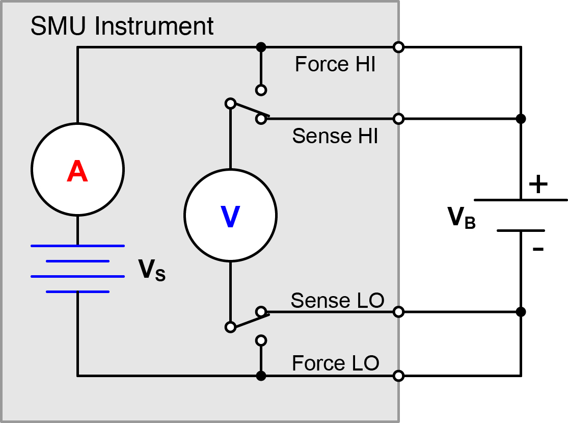
Figure 1: Connecting the SMU to the battery
When in current limit, the SMU instrument acts as a constant current source until it reaches the programmed voltage level. As the battery approaches full charge, the current will decrease until it reaches near zero. Avoid overcharging to prevent battery damage and safety hazards.
When discharging a battery, the SMU instrument operates as a sink, dissipating rather than sourcing power. Its voltage source is set to a level lower than the battery voltage.
The current limit sets the discharge rate. When the output is enabled, current from the battery flows into the HI terminal, so the current readings will be negative. The discharge current should stay constant until the battery voltage drops to the SMU instrument’s voltage source setting.
To set up the test, connect the SMU instrument to the battery as shown in Figure 1. Make a four-wire (remote sense) connection from the instrument terminals to the battery to eliminate the effects of the lead resistance. This allows measuring the battery’s voltage as close to its terminals as possible.
The Force HI and Sense HI output terminals are connected to the battery’s positive (+) terminal; the Sense LO and Force LO outputs are connected to its negative (–) terminal.
When the output is turned off, ensure it is set to the high impedance (High Z) output off-state, so the output relay opens when the output is turned off. This will prevent the battery from draining while the output is off.
Charging and discharging cycles often take several hours, so automating the test is essential. Choose an SMU instrument that has a communication interface (GPIB, USB, or Ethernet) for programmable control.
Program the SMU instrument to perform these steps:
- Set the measurement to a four-wire configuration.
- Set the SMU instrument to measure current. This allows monitoring the load current.
- Use the High Impedance Output Off State.
- Set the SMU instrument to output voltage. Although the unit is set to output voltage, it will be operating in constant current mode because it will be in current limit until it reaches the desired voltage.
- For charging the battery, VS > VB.
- For discharging the battery, VS < VB.
- Turn on the SMU instrument’s voltage source readback function to allow the voltmeter to measure the battery voltage when either charging or discharging.
- Set the current limit (or compliance) to the current level at which the battery is to be charged or discharged. This is the load current of the test.
- Read back the load current, source readback voltage, and relative time stamp.
- Monitor the battery voltage until it reaches the desired level and stop the test.
To illustrate, a 2300mAH AA (1.2V) battery was discharged at a rate of 0.2C using a 460mA load current.
Battery voltage, load current, and relative time were measured every ten seconds until the battery voltage reached the specified level, 1V. The SMU instrument can simultaneously display the load current, battery voltage, and elapsed test time, as well as allowing monitoring readings over the bus.
Mary Anne Tupta is a senior staff applications engineer at Keithley Instruments