Rio de Janeiro, Brazil – January 28 2021: Amazon Echo Dot smart speaker with integrated Alexa voice assistant, home office
Classically, audio tests have assumed that the device being measured has an input and an output, and that the delay from input to output is very short. Such a test scenario is referred to as “closed loop”. However, many devices today – such as smart speakers, portable media players and even mobile handsets – either do not have a direct path between audio input and output, or that path is so inconvenient that a test technique that is not dependent on a closed loop is required: a so-called open loop test.
Closed vs open loop audio test
Closed loop refers to a classic audio measurement technique where a high-quality audio stimulus signal generated by an audio analyser is presented to the input of a device under test (DUT) while the output of the DUT is simultaneously connected to the input of the analyser. This is the simplest case for audio measurement since the analyser “knows” exactly what test signal is presented and can usually automatically compensate for the short amounts of delay typically present.
Open loop refers to any test scenario where the simultaneous connection from input to output is not available. For example, testing a device that plays back music stored in memory or even from the internet.
In this situation, instead of generating a test signal in real-time, the test signal must be pre-generated, stored on the playback device and the analyser must capture and analyse the playback of the signal. The converse example would be the test of a device that records sounds. In this case the analyser will generate the test signal, the DUT will record it, and then the stored recording must be extracted and analysed. In these cases there is no closed path from the analyser’s input to output, open loop measurement techniques are required.
Plainly stated, closed loop testing is much simpler than open loop. In a closed loop test the analyser section of the audio analyser “knows” what signal is being generated and when it is present.
The resulting output signal is immediately acquired and analysed by the instrument’s input section in a single, uninterrupted operation. Any delay between the output and input signal (typically minimal), is removed during the analysis.
Closed loop testing can be used on any device that continuously processes audio, for example, power amplifiers, audio converters (digital-to-analogue converters, analogue-to-digital converters, sampling rate converters, loudspeakers, microphones, or mixing consoles).
When closed loop is required
If closed loop testing is simpler, what drives the need for an open loop test configuration? A variety of device types – playback-only, recording-only, broadcast networks – are the primary determinant for an open loop test setup. Playback-only devices lack an audio input connector (for example, Blu-Ray disc players, media players and media streaming devices), meaning the stimulus signal is required to originate as a digital audio file on the DUT (or storage medium), or on a connected server. Conversely, recording devices record the test signal and provide a digital audio file to be analysed.
There are, of course, many devices, notably PCs, tablets and smartphones, which function as both playback and recording devices. For these, the record and playback functions must be tested separately.
A third class of devices requiring open loop audio test is broadcast networks (including traditional radio and television, as well as media streaming applications). In this case the input to the system is physically separated from the output by a large distance or lengthy network-induced time delay, requiring the use of open loop test techniques.
Creating test signals for playback
Testing the playback function of a device requires placing a high-quality, known audio signal on the device (or playback medium). Basic audio quality metrics such as level, frequency response, total harmonic distortion + noise and crosstalk can be measured using a sine signal. More complicated tests might require signals such as stepped frequency sweeps or pink noise; ultimately almost any signal can be purposed for audio measurement and the appropriate signal will depend on the type of device being used and the desired measurements.
A waveform generator programme (for example, Audio Precision’s APx waveform generator utility) can create .wav files of useful audio test signals at a variety of sample rates, channel counts and bit depths. Many of the test signals are designed to work with the measurements built into the software’s sequence mode and be selectable from the utility menu lists.
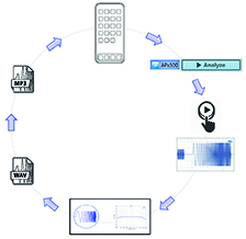
 The process of open loop testing the playback function of an audio device is illustrated in Figure 1.
In this case the outputs from the DUT are connected to the audio analyser inputs (in this example, using APx500 software). The first step is to configure the generator and save the .wav file of the stimulus signal. Some devices will not play the .wav files directly, in which case the file should be encoded to a suitable format, for example, .mp3.
Next, the stimulus file should be installed on the DUT for playback and analysis. When the test signal is played from the DUT the audio analyser acquires the signal from the DUT and analyses it to produce audio quality metrics.
Testing acoustic playback devices (for example, a Wi-Fi or smart speaker) in an ordinary room will produce room reflections. Measurements such as the acoustic response measurement can be used to “window” the impulse response to remove these reflections. The time window will need to be set after the signal is acquired.
Testing the record function
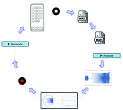
To test the record function of a device, the set up is reversed. The audio analyser generator is connected to the DUT inputs and the analyser’s input connector is set to file (digital units), meaning the input will come from a .wav file. The incoming signal from the analyser is recorded by the DUT to a file, which is then analysed by the audio analyser (see Figure 2).
 The first step is to set up the audio analyser to generate the stimulus signal and start recording on the DUT. When the signal recording is complete, a .wav or .mp3 file of the recording needs to be saved and then transferred to the PC running the analysis software. (Depending on the software, an .mp3 file may need to be decoded into a .wav file.) The input file can then be analysed.
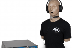
Depending on the source of the signal, some additional steps may be needed for acoustic devices. For example, a signal generated by a mouth simulator (a special loudspeaker with prescribed opening dimensions for generating speech signals) will require the mouth simulator to be calibrated and its output equalised to have a flat frequency response to ensure it faithfully reproduces speech signals.
Traditionally, audio measurements have relied on closed loop testing. Closed loop testing remains the best way to characterise devices such as loudspeakers, microphones, amplifiers and audio converters. However, as smart devices, streaming playback services and cloud-connected devices come to dominate the landscape of consumer audio the need to be able to make measurements on these open loop devices increases.
 Electronics Weekly Electronics Design & Components Tech News
