“TI is building the industry’s most comprehensive portfolio of Arm Cortex-M0+ based MCUs,” claimed TI MCU v-p Vinay Agarwal.
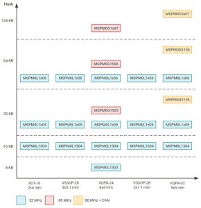
Two be known as MSPM0, there are initially two sub-groups, one clocking at 32MHz and the other at 80MHz.
- MSPM0L..
32MHz CPU, up to 64kbyte flash, up to 4kbyte ram
Analogue options: zero-drift op amps, TIA, 12bit 1Msample/s ADC, fast comparator - MSPM0G..
80MHz CPU, up to 128kbyte flash, up to 32kbyte ram
Analogue options: zero-drift op amps, dual 14bit 250ksample/s ADCs, dual 12bit 4Msample/s ADCs, fast comparators, 12-bit 1Msample/s DAC
CAN interface options up to 5Mbit/s, including 2.0A, 2.0B, or FD (flexible data-rate)
This is the first time a zero-drift op-amp, which could ease precision sensor interfacing considerably, has been seen in an MCU by Electronics Weekly.
The MSPM0L130x data sheet (see below) gives a glimpse of the chopping op-amp: 0.5µV/°C drift, 10pA input bias and integrated programmable (up to 32x) gain stage. It also reveals a two-mode comparator: 40ns propagation delay fast mode and 1µA low-power mode, with an 8bit reference DAC.
Packages will range across 16 to 64pads, and the smallest flash size planned is 16kbyte.
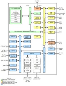
 Power-wise, picking the MSPM0G110x range (block diagram left) almost at random, they will run at 96µA/MHz (CoreMark), sleep at 200µA (4MHz), stop at 50µA (32kHz), stand-by at 1.5µA (RTC and SRAM active) and shut-down to 100nA (with IO wake).
For prototyping, the there are hardware development kits for MSPM0L1306 and MSPM0G3507, and there will be a MSPM0 software development kit with drivers, libraries, over 200 code examples and sub-system designs.
“Design support resources and coding tools, including graphical tools that streamline device configuration, help designers code once and then scale across future MSPM0-based designs”, said TI.
See the MSPM0 MCU on TI’s stand at embedded world – number 215 in hall 3A. or look up MSPM0 on this web page.
 Electronics Weekly Electronics Design & Components Tech News


